The Microscopic Staircase: Why a Machined Curved Surface Can Never Be Truly Smooth
Imagine holding a high-precision metal component in your hand—a sleek turbine blade, a smooth automotive mold, or a custom medical implant. Under the bright lights of the shop floor, the complex, flowing curves look completely liquid. You run your fingers over the metallic surface, and it feels remarkably smooth, almost like polished glass.
Satisfied with the craftsmanship, you put it down, assuming that your 5-axis CNC milling machine has created a mathematically perfect curve.
However, if you took that exact same component and placed it under a high-magnification microscope, your eyes would deceive you no longer.
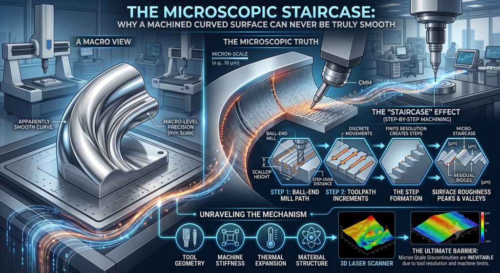
That flowing, organic curve would instantly disappear. In its place, you would see a landscape of microscopic jagged steps, ridge lines, and wave-like valleys. It looks less like a smooth slide and more like an ultra-fine, microscopic staircase carved into the metal.
Why does this happen? Can a modern, multi-million-dollar CNC machine ever cut a truly, mathematically smooth curved surface?
The short, surprising answer is no—it is physically impossible.
Let’s take an easy, math-free look at why 3D curved machining will always be a game of microscopic approximations, and how engineers use clever strategies to make these hidden staircases as tiny as possible.
The Core Dilemma: Round Tools Cutting Flat Lines
To understand why curves are impossible to machine perfectly, we need to look at how CNC machines and computer software talk to each other.
In the digital world of CAD (Computer-Aided Design), a 3D curve is a pure mathematical concept. It is infinitely smooth. You can zoom in a million times on a computer screen, and the curve will never break down into straight lines.
However, a physical CNC machine does not understand “infinite smoothness.” It operates in the real world, guided by motor axes (X, Y, and Z) that move in straight line segments or simple circular arcs.
To bridge this gap, your CAM (Computer-Aided Manufacturing) software has to translate that pure digital curve into a language the machine understands: a long string of tiny, straight movements.
The Pixel Analogy
Think of a curved surface on a CNC machine like a round image on a computer monitor:
- If your screen has low resolution, a circle looks jagged, blocky, and pixelated.
- If you upgrade to a 4K display, the pixels get so small that your human eyes perceive a smooth circle.
However, no matter how high the resolution is, if you zoom in close enough with a magnifying glass, the image is still made of square pixels.
In CNC machining, every line of G-code represents one of those “pixels.” A toolpath cutting a complex curve is simply thousands of tiny, straight line segments connected together. Because every individual segment is straight, the resulting metal surface is fundamentally a series of tiny flat facets, not a true curve.
The Scallop Effect: The Mark of the Round Tool
Even if a machine could make infinitely small straight moves, it faces a second physical barrier: the shape of the cutting tool itself.
To cut smooth 3D curves, machinists usually use a Ball-Nose Endmill—a cutting tool with a rounded, dome-like tip.
Imagine pushing a lawnmower across a bumpy hill. To cover the entire hill, you have to make multiple parallel passes back and forth. Because the blades and wheels leave subtle tracks, every time you overlap your passes, a tiny peak or ridge of grass is left behind between the rows.
The exact same thing happens when a ball-nose endmill sweeps across a metal part:
- The rounded tip carves a small, dish-shaped trough into the metal.
- The machine steps over by a fraction of a millimeter to take the next pass.
- Where the two rounded cuts meet, a tiny, crest-like ridge of uncut metal remains.
In the machining world, these microscopic ridges are called scallops or cusps.
No matter how tiny you make the step-over distance between passes, as long as you are using a round cutting tool, there will always be a scallop height left behind. You can make those ridges smaller than a red blood cell, but you can never reduce them to absolute zero.
The 3 Ways Machinists Tame the Invisible Staircase
Since true mathematical smoothness is impossible, the goal of precision manufacturing isn’t to eliminate these microscopic ridges entirely—it is to make them so tiny that they don’t matter.
Here is how modern machine shops fight the battle against the staircase effect:
1. Tightening the “Tolerance Band”
In CAM software, programmers can adjust a setting called machining tolerance. This tells the computer how closely the straight-line toolpath must stick to the ideal digital curve.
By tightening this setting, the software breaks the curve down into tens of thousands of microscopic line segments instead of hundreds. The machine takes much longer to run the program, but the “pixels” become virtually invisible.
2. Shrinking the Step-Over Distance
To minimize the height of the scallop ridges, programmers drop the step-over distance down to tiny fractions of a millimeter. When the rounded passes are packed extremely close together, the ridges flatten out, creating a surface that feels completely smooth to human touch.
3. Barrel Cutters (Circle-Segment Tools)
One of the coolest modern innovations in 3D machining is the Barrel Endmill (or Circle-Segment cutter).
Instead of using a small ball-shaped tip, these tools have a large, subtle arc built into their side profile—like a massive barrel.
When used on a 5-axis CNC machine, the large curved edge of the barrel tool sweeps across the metal, covering a huge area in a single pass while leaving virtually no scallop height behind. This allows shops to achieve mirror-like finishes in a fraction of the time.
The Final Polish: Leaving the Machine Behind
Because a milling machine can only approximate a curve, high-precision industries—like automotive mold-making or optical lens manufacturing—rarely stop at the CNC machine.
To achieve true, mirror-like smoothness, parts go through post-processing operations like hand polishing, abrasive flow machining, or chemical etching. These processes physically knock off the microscopic peaks of those scallop ridges, smearing and smoothing the surface at an atomic level.
The Takeaway: Perfection is an Illusion
The next time you admire a sleek, beautifully curved metal object, remember the secret hidden beneath its shiny exterior.
In precision manufacturing, “smoothness” is an illusion created by making tiny errors so small that the human eye and touch cannot detect them. A 3D machined curve is never truly smooth—it is just a masterclass in microscopic physics, where millions of tiny straight lines and rounded cuts work together to create the appearance of perfection.
Get more info, please visit our CNC Turning Parts or Products.
Contact us for your customized metal parts.
How does your shop handle finishing passes on complex 3D surfaces? Do you rely on tight step-overs, barrel tools, or manual polishing? Let’s share your experiences in the comments below!